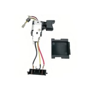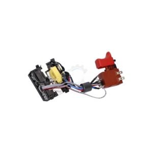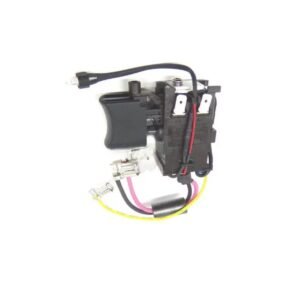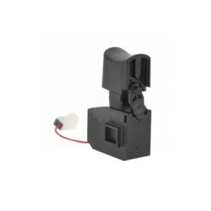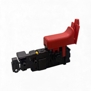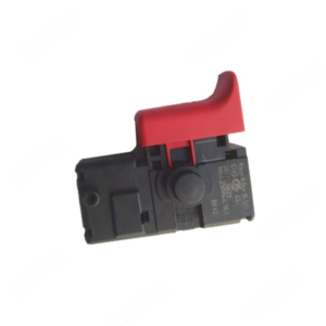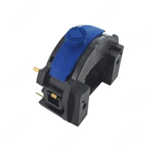
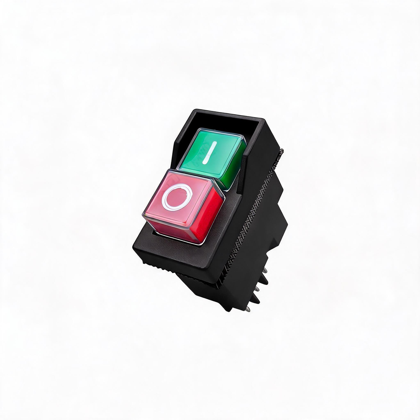
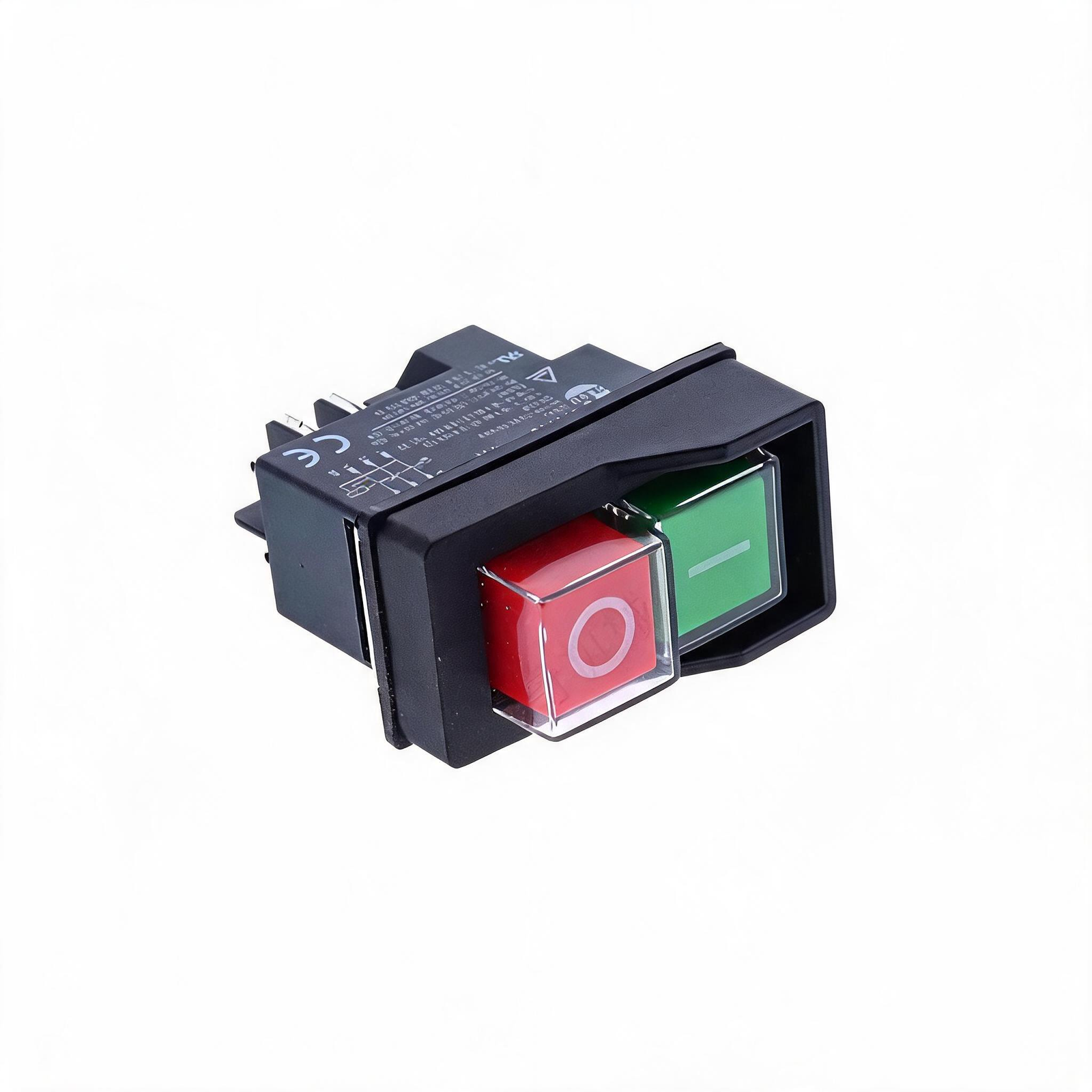
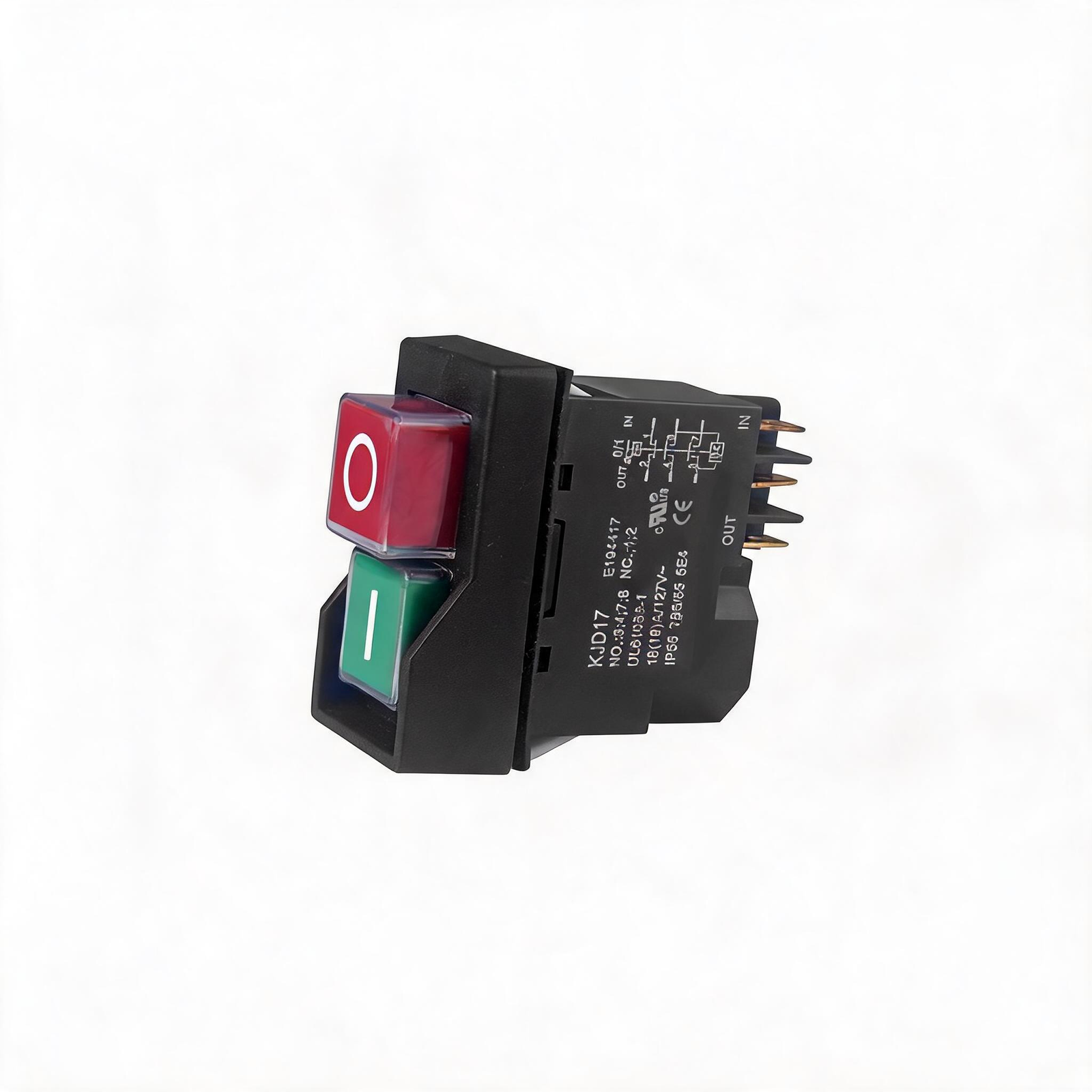
Diagnostic Data: Why the N603746 Switch Fails
A jobsite table saw switch is not a standard mechanical toggle; it is a magnetic relay system designed for safety. When power drops, the internal electromagnet loses its charge, snapping the contacts open so the saw does not violently restart when the grid comes back online. Over time, heavy vibration and fine sawdust infiltrate the plastic chassis, causing the magnetic coil to overheat or the physical contacts to carbon-score. When this happens, the switch can no longer hold the electrical load.
1️⃣ Relay Hold Failure
The motor spins up when engaged but dies instantly upon release. The electromagnet has burned out and can no longer lock the armature in the closed circuit position.
2️⃣ Mechanical Bind
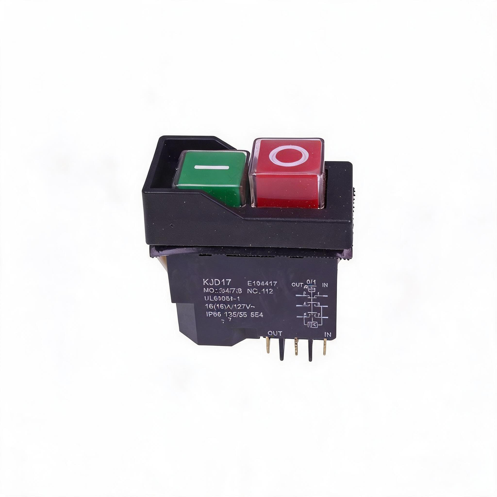
The red emergency stop paddle feels stiff or refuses to click. Sawdust has bypassed the main seal and packed into the spring mechanism, preventing safe shutdowns.
3️⃣ Dead Actuator
You press the start button and get zero response, despite confirming 120V at the wall. The internal silver contacts have oxidized or arc-welded into an open state.
Component Evaluation: OEM Spec vs. Cheap Knockoffs
| Component Parameter | Cheap Aftermarket Failure Points | OEM-Spec N603746 Replacement |
|---|---|---|
| Internal Contacts | Thin brass plates weld shut under rip-cut amp loads. | ✅ Silver-cadmium pads for maximum arc suppression. |
| Magnetic Coil | Low-gauge wire overheats and drops the relay mid-cut. | ✅ High-gauge copper winding for sustained heavy loads. |
| Housing Chassis | Brittle plastic cracks when seating the mounting screws. | ✅ Impact-resistant ABS polymer withstands jobsite abuse. |
Teardown & Replacement Workflow
Bezel Extraction
Remove the mounting screws securing the black switch plate to the main saw housing. Carefully pull the assembly forward to expose the wiring harness.
Line & Load Identification
Before pulling any wires, photograph the terminal layout. Identify the “Line” (power from wall) and “Load” (power to motor) spade connectors to prevent phase crossing.
Terminal Transfer
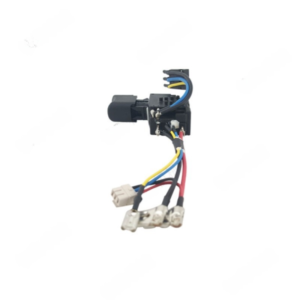
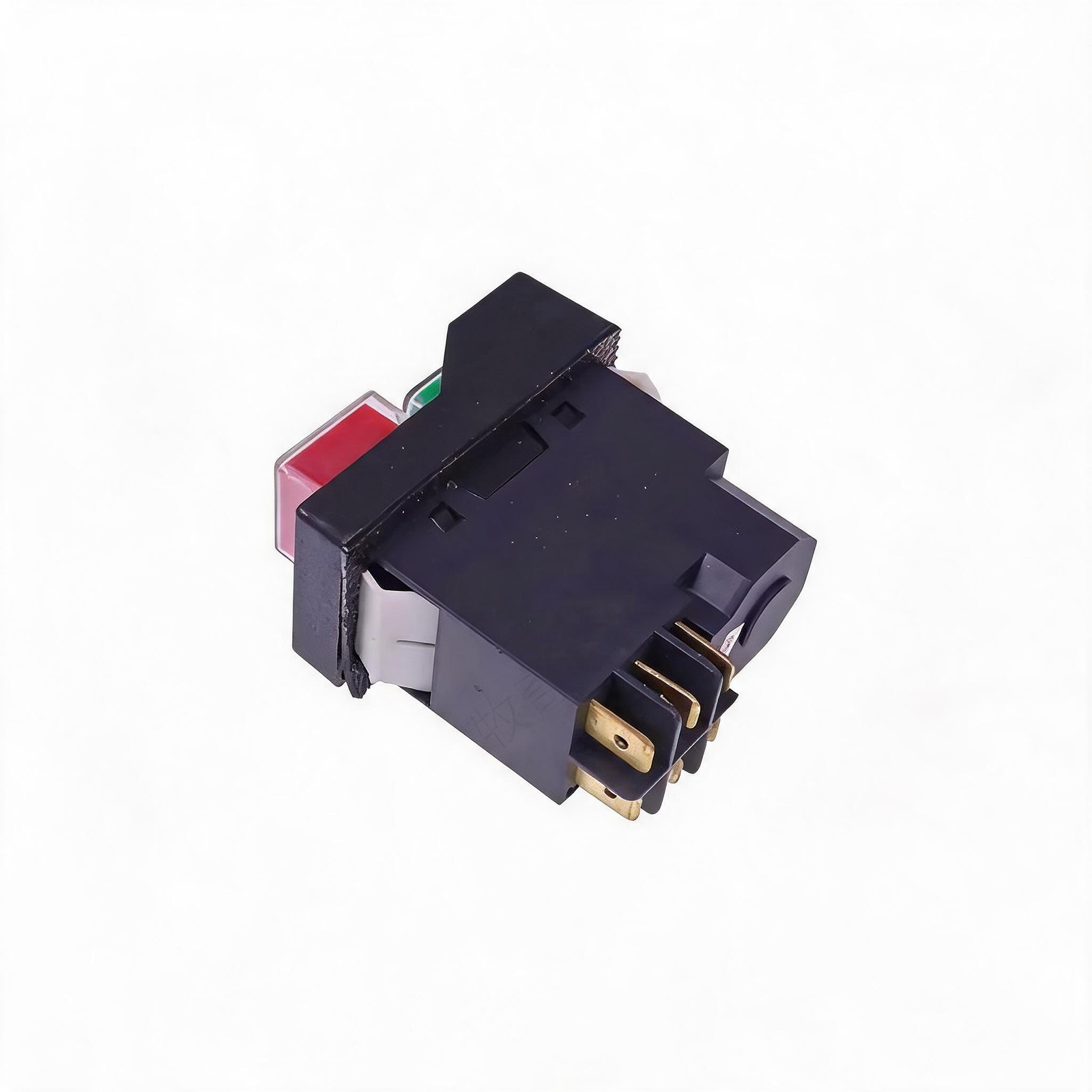
Use needle-nose pliers to disconnect the spade terminals from the old switch. Transfer them one-by-one to the corresponding ports on the new N603746 switch.
Hardware Seating
Push the wired assembly back into the chassis cavity, ensuring no wires are pinched against the metal frame. Torque the bezel screws by hand.
Fitment & Cross-Reference Data
Diagnostic Q&A
Safety Notes
- Total Power Isolation: Never rely on a tripped breaker. Physically unplug the power cord from the wall outlet before removing the switch bezel.
- Spade Terminal Tension: If the female spade connectors on your saw’s wiring harness feel loose when sliding them onto the new switch, crimp them slightly with pliers. A loose connection causes electrical arcing and will melt the new switch.
- Torque Limits: Drive the bezel mounting screws by hand. Using an impact driver will crack the plastic housing plate.
The most definitive symptom is the “hold-to-run” fault. If the saw powers up when you press the green button but instantly shuts off the moment you release pressure, the internal magnetic holding coil has failed and the entire N603746 unit must be replaced.
Yes, this OEM-spec replacement switch is a direct drop-in for the 7491RS, 7485, and several other compatible 10-inch and 8-1/4 inch jobsite table saws utilizing this specific bezel design.
No soldering is required. The switch utilizes standard male spade terminals. You simply pull the female wire connectors off the old switch and push them directly onto the new unit. Always transfer one wire at a time to avoid crossing the line and load phases.