Product Overview
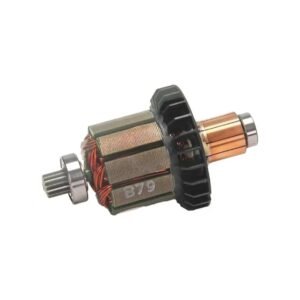
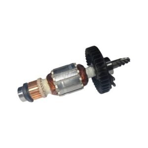
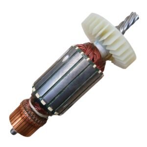
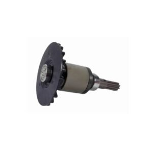
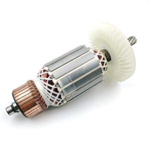
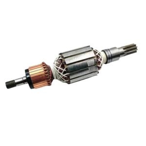
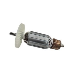
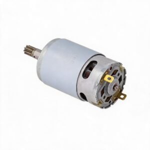
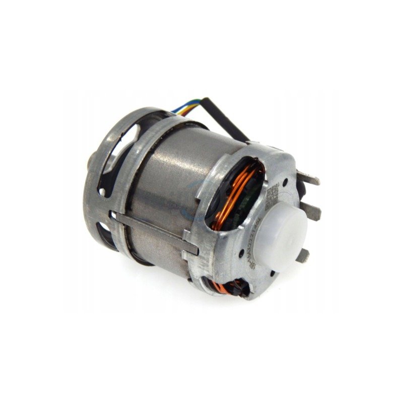
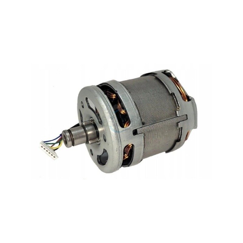
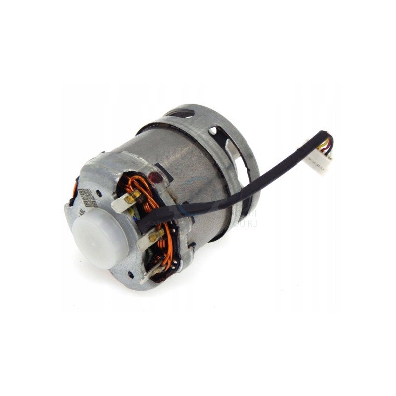
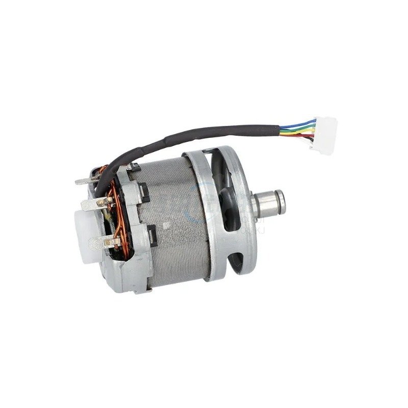
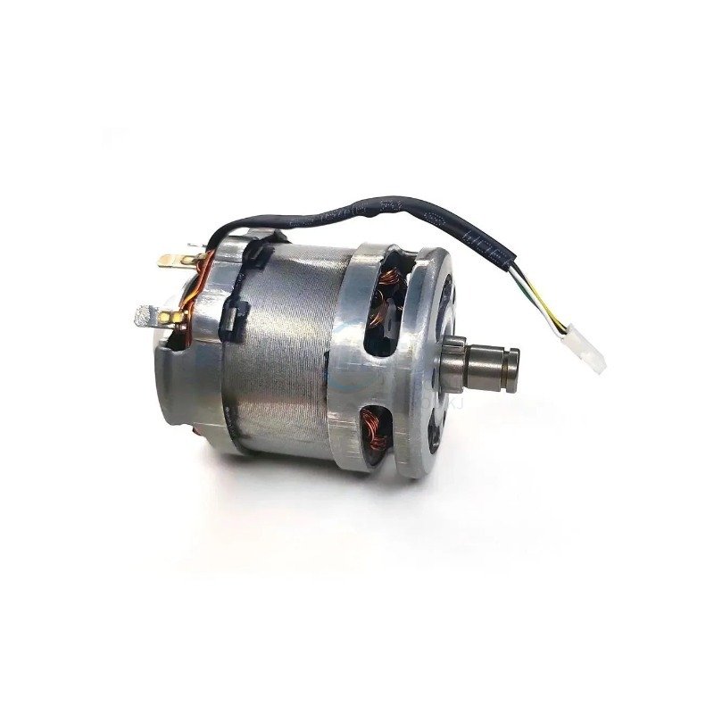
The 1607000CA4 Brushless Motor Assembly is a precision-engineered direct-fit replacement for the 18V cordless angle grinders and straight grinders that share this platform. This unit integrates the rotor, stator, Hall-effect sensor board, and thermal management components into a single pre-tested assembly – eliminating the need for individual component diagnosis and rework.
Designed for professional repair technicians and equipment maintenance specialists, this motor restores factory-spec performance to tools exhibiting loss of power, intermittent operation, excessive sparking (in brushed variants), or complete failure to start. The 600g assembly weight matches the original equipment specification, preserving the tool’s engineered center of gravity and reducing operator fatigue during extended use.
💡 Pro Tip – Teardown Diagnostic: Before replacing the motor, perform a no-load amp draw test with a DC clamp meter. A healthy 18V brushless motor should draw approximately 2.5–4.5A at no load. Draws exceeding 8A at idle indicate either a failing motor controller or shorted windings – both resolved by this complete assembly swap. Always disconnect the battery pack and discharge the power filter capacitors (wait 60 seconds) before disassembly.
Diagnostic & Fitment – When to Replace
Specification Comparison
| Specification | Worn / Generic Aftermarket | FixPartHub Precision Replacement ✅ |
|---|---|---|
| Rotor Balance | Unbalanced – vibration & bearing wear | Factory dynamic-balanced to ≤ G2.5 |
| Winding Insulation | Substandard Class A – thermal degradation | Class F insulation – 155°C rated |
| Magnet Material | Low-grade ferrite – flux density drop | High-grade neodymium – full flux retention |
| Mounting Precision | Loose tolerances – misalignment risk | CNC-machined housing – exact fit |
| Thermal Management | No heat-path optimization | Enhanced heat-sink interface – extended duty cycle |
Teardown & Replacement Workflow
Compatibility – Cross-Reference & OEM Part Numbers
Diagnostic Q&A
❓ Q: My grinder runs but slows down significantly under load – is this definitely a motor issue?
A: Not always. Test with a fully charged battery pack first. If the issue persists with known-good batteries, the motor is the primary suspect. Use a DC clamp meter to check amp draw – excessive current under load points to winding degradation. The 1607000CA4 replacement resolves this completely.
❓ Q: Will this motor work with my GWS18V-115C if the tool has a different production date?
A: Yes. The 1607000CA4 motor assembly is the standardized replacement across the entire GWS18V-1xx and GGS18V-2x platform. Production date variations do not affect motor mounting or connector compatibility – the platform uses a unified motor interface.
❓ Q: What torque spec should I use when reinstalling the motor housing screws?
A: Apply 1.8–2.2 Nm (16–19 in-lbs) to the housing screws. Over-torquing can deform the plastic housing and cause bearing misalignment. Under-torquing allows vibration to loosen fasteners during operation.
Safety Notes
- 🔴 Always disconnect the battery pack before beginning any disassembly or motor replacement procedure.
- ⚡ Allow capacitor discharge time – wait a minimum of 60 seconds after battery removal before handling internal components.
- 🔧 Use correct torque values – over-torquing housing screws can damage the motor housing and affect bearing alignment.
- 🧤 Wear ESD-safe gloves when handling the motor assembly to prevent static discharge damage to Hall-effect sensors.
- 📐 Verify shaft alignment before final assembly – the output shaft should spin freely with no binding or grinding feel.
- ✅ Perform a no-load test before reinstalling the tool’s outer housing – verify smooth operation and correct RPM response.
A: Yes. The 1607000CA4 is designed as a universal fitment for the 18V platform shared by angle grinders (GWS18V series) and straight grinders (GGS18V series). Always verify your tool’s model number against the compatibility list before ordering.
A: Common symptoms include intermittent starting, stuttering or hesitation when the trigger is engaged, significant power loss under grinding or cutting load, excessive heat generation from the motor housing during normal operation, and a burnt odor indicating winding insulation breakdown.
A: No. The complete motor assembly includes the rotor, stator, and Hall-effect sensor board. The tool’s main controller board remains in place – simply disconnect the old motor’s harness and plug in the replacement unit.
A: Perform a no-load run test with the housing open. The motor should spin smoothly with minimal vibration. Use a tachometer to verify RPM matches the tool’s specification. Run the tool under light load for 30 seconds and check for abnormal heat buildup or noise.